Custom Firmware for DJI Mini 2
In this blog post, I’ll take a look at the DJI Mini 2 (and related) drones, and describe a way to flash arbitrary, modified firmware.
Hardware Overview
In October of 2019, the chinese company DJI released the Mavic Mini 1, a 249g-class UAV. The DJI Mini 2 was released in November of 2020, and is also a 249g-class UAV. Finally, in summer of 2021, the DJI Mini SE was released as upgrade of the Mavic Mini 1 and a lower-cost version of the Mini 2.
The DJI Mini series are distinctively different from other modern drones released by DJI, because it is largely based on off-the-shelf semiconductors.
In contrast, the 2022-released DJI Mini 3 Pro, also a 249g-class UAV, is essentially a shrinked-down DJI Air 2S, retaining the core chipset consisting of 3 in-house DJI chips.
This makes the Mavic Mini 1, Mini 2 and Mini SE interesting from the perspective of running own code, which should be the focus of this blog post. In general, the level of sophistication for this drone is relatively high; it will be hard to find a quadcopter with a similar feature set in this price range, especially considering that often these can be obtained cheaply when damaged (and often be repaired).
Let’s dive into the hardware. I’ll focus on the DJI Mini 2, but - other when noted - the DJI Mini 1 and Mini SE are largely very similar.
Flight Controller
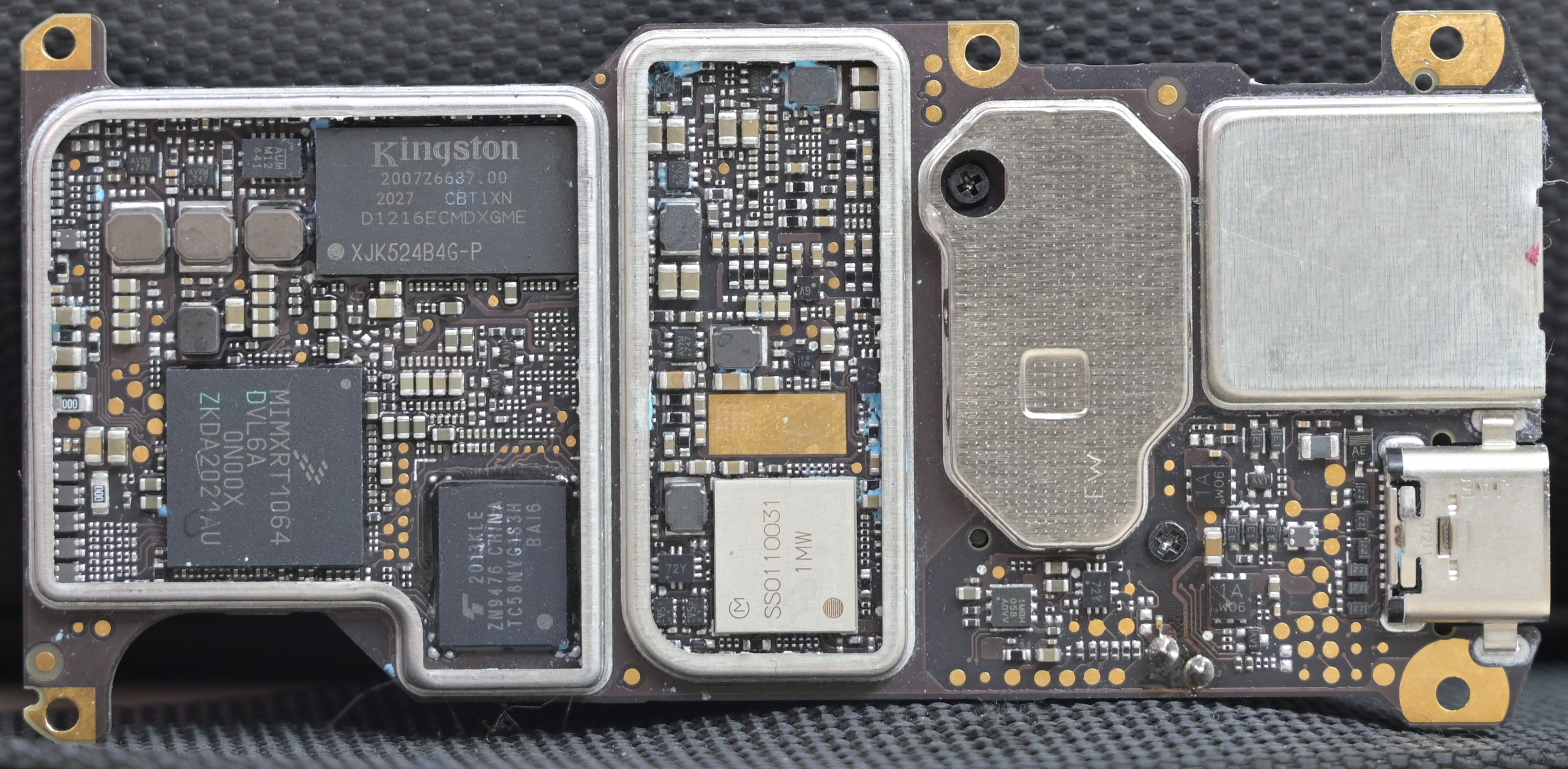
The Mini 2 uses an NXP iMXRT1064 for its flight controller. It does the following:
- Control of motor speeds (via PWM to ESCs)
- Sensor fusion and stabilization (processing IMU data)
- Coarse navigation, including return-to-home
- Receiving control inputs and translating them to flight attitude requests
- Battery monitoring
- Communication hub for essential (flight-critical) communication between ESCs, RF-Link, WiFi and the Linux/Camera subsystem; this is all using UART communication, with the DUML protocol.
- Gimbal handling
The Mavic Mini 1 uses an NXP iMXRT1060, which is very similar to the iMXRT1064, except it uses an external SPI flash (connected to the first FlexSPI controller), whereas the iMX1064 has an embedded (SiP’ed) Winbond SPI chip (connected to the second FlexSPI controller). The actual silicon is the same; apart of the memory layout differences (first vs. second FlexSPI controller), the software is largely identical. The MiniSE also uses the iMXRT1064.
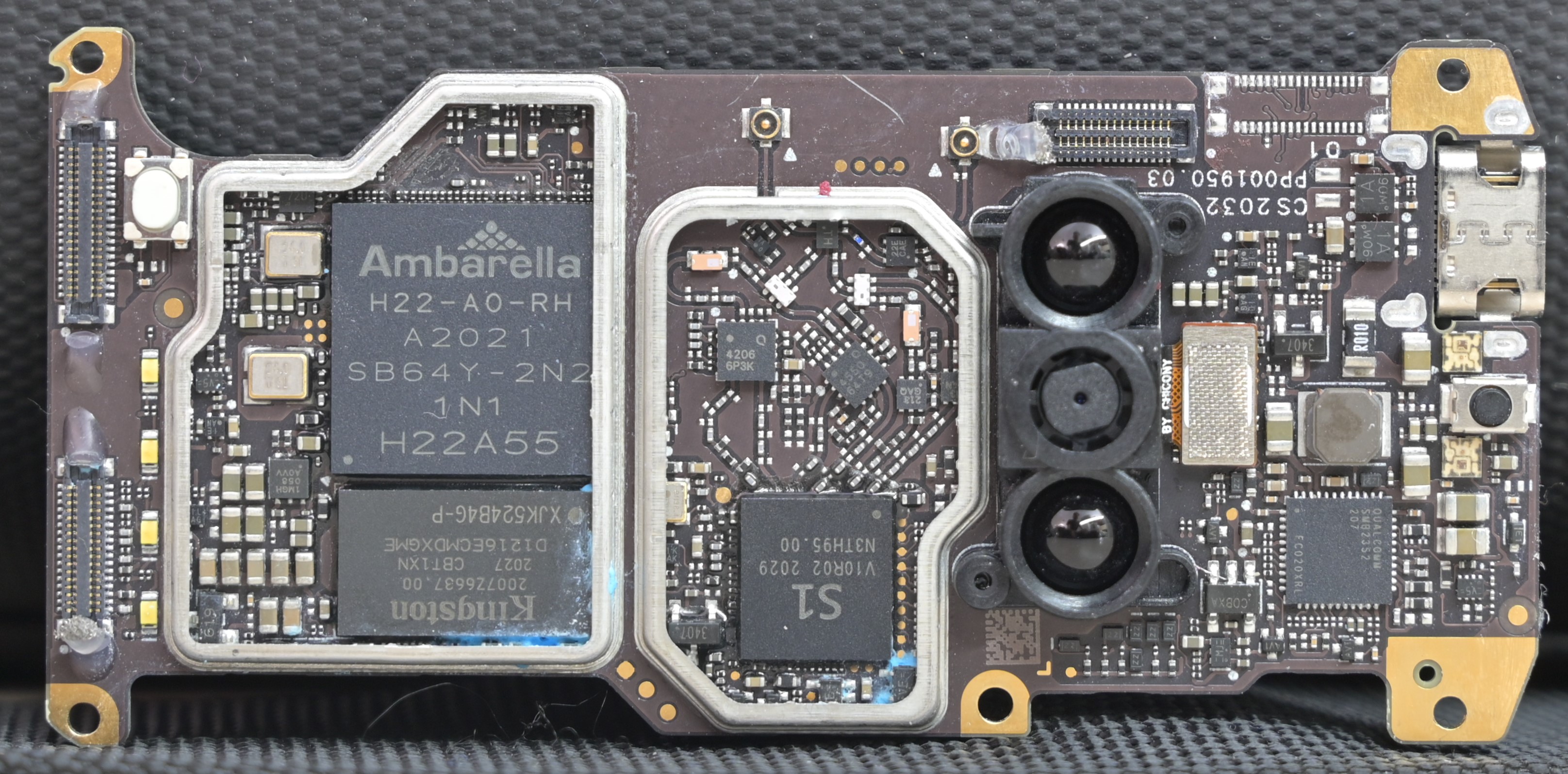
The camera data is not processed by the iMX RT. Instead, an Ambarella H22 (seemingly very similar to the Ambarella S5L) is used side-by-side.
The Ambarella runs a custom RTOS and Linux in an asymmetric multiprocessing setup, where a core is dedicated to the RTOS and the other cores are running Linux.
The Ambarella has a Quad-Core Cortex-A53, but on the Mini 2 a 32-bit kernel and userland is used; the RTOS also executes in 32-bit mode. Only the boot-ROM and initial bootloaders run in AArch64 mode.
There’s 2GB of memory.
The camera itself is the same as in the DJI Mavic Mini 1 and Mini SE; in fact, the complete hardware gimbal assembly, which contains the camera, is identical to the DJI Mavic Mini 1 gimbal, with the exception of a (purely cosmetical) “4K”-badge. (In fact, I don’t think there is a reason why the DJI Mavic Mini 1 couldn’t also do 4k video…)
The gimbal consists of 3-axis which each contain a 3-phase motor driver with 2 analog hall-sensors. The flight controller uses these for coarse positioning, but the fine control is done using an dedicated IMU that is within the camera assembly.
A TI SmartBattery chipset is contained in the Mini 2 batteries. The Flight Controller talks with the chipset in the battery over I2C and translates DUML battery queries to the specific implementation. Batteries are authenticated and state-of-charge information is also used to control flight, such as forced Return-to-home. Some of the battery thresholds are stored in flight controller parameters, for which there is a “standard” mechanism to query and change them (within limits) via DUML.
The drone uses sensor fusion from an IMU, a GPS chipset and dead reckoning, i.e. estimating the theoretical flight path based on flight parameters and environmental estimations such as wind speed.
All of these calculations are done on the Flight Controller.
For accurate positioning without drifting, the drone uses a low-resolution downvision sensor that is processed in the Ambarella RTOS. On top of this, it utilizes a Time-of-Flight chip to measure the height over ground. The combination of these data sources and the IMU and GPS data allows for a very precise positional control. The visual calculations are done on the Ambarella core in the RTOS, but the data is fed back into the flight controller.
Navigation
The Mini-series does not support waypoints as a user-visible feature. However, the flight controller support as “navigation”-mode where waypoints are produces by a Linux process on the Amberella-side. This is used to provide navigation for the automated “Quickshots”, for example to automatically fly a circule around a point-of-interest.
The Flight Controller also supports missions like “return-to-home”, “forced-landing” etc.
RF Link
The RF link is the major difference between the DJI Mavic Mini and Mini SE, and the Mini 2. All 3 aircrafts have WiFi support, and for the Mini 1 and SE, this is also the only supported RF link for controlling the drone. The Mini 2, however, adds “OcuSync”-Support by utilizing the DJI S1 chip. “OcuSync” is essentially an RF protocol that is related to LTE on a physical layer - it shared LTE downlink’s OFDM, frame synchronization, scrambling and error correction mechanisms, but deviates on the upper layers.
Software
The software stack is very similar to the software stack used on other DJI drones; DJI uses the same components but depending on the drone hardware executes them differently. For example, the security aspects on the DJI Mini 2 are executed on the flight controller, whereas for other drones, they are executed in TrustZone applications (TrustZone is not used on the DJI Mini 2).
Logging
Very extensive logging is producing during flight. These “flight recorder” messages are produces at various rates in the Flight Controller (and some other sources), and are then pushed into the “blackbox” component, which is a Linux usermode process (i.e. on the Ambarella) and pushes these recordings - symmetrically encrypted - into logfiles in a dedicated (“blackbox”) NAND partition.
Tools exist to read these log files but only few of them can handle the Mini 2-specific encryption. The messages are raw binary structures, but the Mini 2 flight controller firmware contains embedded information on how to parse these logs.
Security
DJI uses the “Bus Encryption Engine” on the iMXRT1064. This means that all flash contents are encrypted with a dedicated, fused key. Encryption utilizes AES-ECB, i.e. per-block encryption without any authentication or chaining, allowing random-access (for each 16 byte) without having to load other data. We’ll talk about flight controller security (and how to hack it) later; for now, let’s assume that the flight controller is actually running secret and authenticated code (an assumption that we’re able to change, of course).
The Ambarella chip itself does not have any security. It has a very small embedded ROM (at FFFF0000, 0x1000 bytes), which evaluates a bootstrap pin to chose the boot path - typically the regular NAND flash, but it also supports eMMC and USB. It fetches the first 0x800 bytes, and then jumps there - no verification, no secureboot, no anything.
In the regular boot chain, this “bootstrap” handler then enables DRAM, copies itself to DRAM, then loads the bootloader NAND partition table, and loads the “BOOTLOADER” partition.
“BOOTLOADER” is Ambarella’s “AmBoot” bootloader (that Ambarella ships the source code with their SDK). DJI customized it slightly; typically AmBoot has a serial shell, but the ability to reach it was removed. AmBoot then finds the next stage bootloader, called “LDR1”, which is the first DJI-specific code. All of this code is still 64-bit.
“LDR1” then starts the boot security chain. LDR1 loads the RTOS and Linux image, which are stored in IM*H-containers (DJI’s encrypted/authenticated image format). LDR1 stores an embedded public key for authentication, and a transport (called “factory”) key for encrypted+authenticated communication with the flight controller. LDR1 then fetches the encrypted keys and a hash of the public key from FC.
Starting from LDR1, all further code is authenticated - the RTOS and Linux image are, as described, stored in authenticated IM*H-containers, and a dm-verity layer (with the root hash embedded in the Linux image) is used on top of the rootfs. But naturally this is only secure as long as LDR1 is not modified.
Secure Debug
LDR1 also queries a “Secure Debug” state from the flight controller. If it is set, it will set the right kernel command line arguments to enable adb and other functionality.
This communication is symmetrically protected with a key that is embedded into LDR1. To make extraction of the key harder, a whitebox-crypto approach is used to hide the key. However, a bit of Unicorn makes it trivial to execute this part of LDR1 and retrieve the key.
LDR1 also uses this to retrieve encryption keys from the flight controller. A key called UFIE is used to decrypt updates, another key called TKIE (and yet another TBIE) is used to decrypt boot images. By sniffing the UART traffic between the flight controller and Ambarella, and using the whitebox’ed crypto key, we can obtain this key material.
Firmware updates
Armed with these keys, we can use the dji-firmware-tools-repository to decrypt firmware updates.
Firmware updates can easily be downloaded using Dank Drone Downloader, which maintains mirrors for all publicly (and some not-quite-publicly) released firmware images.
A firmware image consists of multiple IM*H-files; DJI uses module codes to differentiate the “target” for these. 0306 is the module ID for the flight controller, 0100 is the module ID for the Ambarella part (including LDR1, RTOS, Linux kernel and rootfs). The firmware can be decrypted using the .dji_imah_fwsig.py tool.
The resulting image is compressed with lz4. I had not a lot of success with command-line tools, but the following python tool unpacks such an image:
import lz4.frame
import sys

d = open(sys.argv[1], "rb").read()
open(sys.argv[2], "wb").write(lz4.frame.decompress(d))
The resulting image contains LDR1, and then a few IM*H-images, and finally two squashfs-Images for / and /system.
At that point, we can investigate all code running on the Ambarella core (and identify all the stolen GPL components).
Flashing Ambarella
But remember the Amberella ROM? It also supports booting from USB; this is typically used for flash recovery. Ambarella ships a standard tool called “AmbaUSB” with their SDK, which some other manufacturers of Ambarella-based devices offer as a download to end users.
On the DJI Mini 2 (and equally on the Mavic Mini 1, and very likely also on the Mini SE), there’s a test pad that can be asserted to enforce booting in USB mode. The ROM is very simple - which means that the USB bootloader is also very simplistic. It enumerates as a USB device, and then supports reading, writing memory (32-bit at a time to/from arbitrary addresses), and jumping into uploaded code.
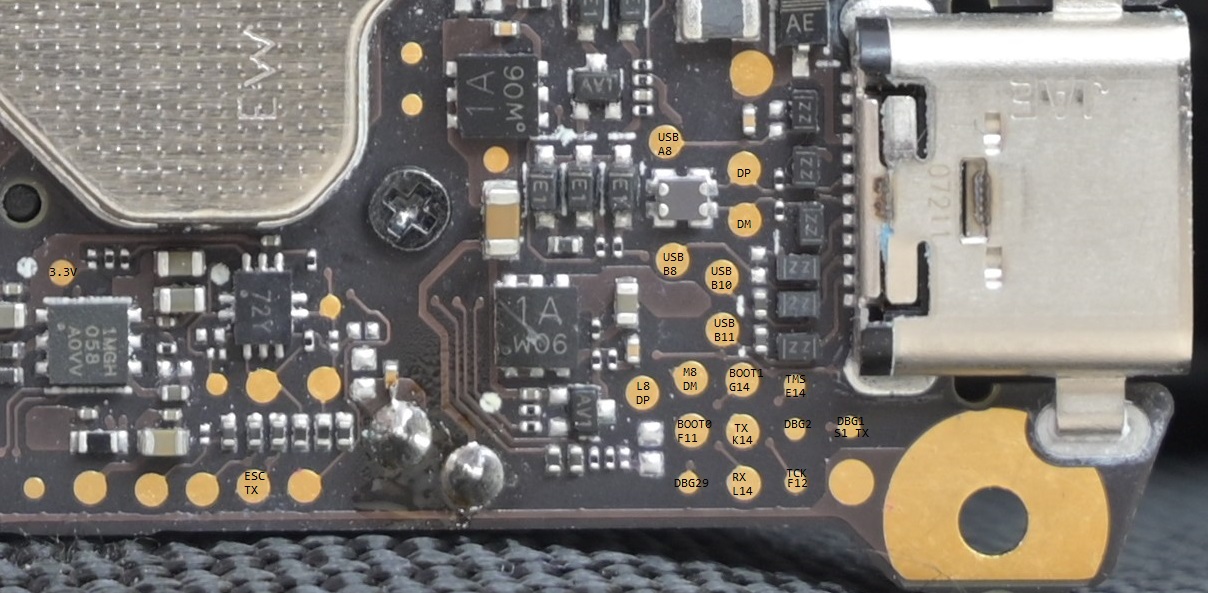
Debug Header
Using the testpoint is one way to access these pins; another one is a dedicated, unpopulated debug header right next to the ESC-to-core flex cable. On the Mini 2, it’s a 2x17 connector.
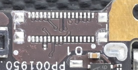
Unfortuantely I don’t have the full pinout but the relevant parts are here:
| Num | Desc. | Num | Desc. |
|---|---|---|---|
| 18 | GND | 1 | DBG1 S1 TX |
| 19 | 2 | DBG2 S1 RX (?) | |
| 20 | 3 | iMXRT TMS | |
| 21 | 4 | iMXRT TCK | |
| 22 | 5 | iMXRT LPUART1 TX | |
| 23 | 6 | iMXRT LPUART1 RX | |
| 24 | 7 | iMXRT BOOT1 | |
| 25 | 8 | iMXRT BOOT0 | |
| 26 | 9 | iMXRT DM | |
| 27 | 10 | iMXRT DP | |
| 28 | 11 | « 3.3V source » | |
| 29 | USB BOOT | 12 | |
| 30 | Ambarella TX ttyS1 | 13 | |
| 31 | Ambarella RX ttyS1 | 14 | |
| 32 | Ambarella TX ttyS0 | 15 | |
| 33 | Ambarella RX ttyS0 | 16 | |
| 34 | GND | 17 | GND |
Pins 30 and 31 are by default muxed to the serial port that is used by RTOS. This is also the port used by my affr tool for debug spew.
Pins 32 and 33 are by default muxed to the UART used for the Linux console. It outputs a bit of the Linux boot process, but then console output is disabled and the UART is re-used for DUML communication.
The debug header for the Mavic Mini 1 is very similar, but short by 2 rows (likely due to missing S1 pin), so it is a 2x15 pin connector. I did not reverse all the pins but the relative position appears to be the same.
| Num | Desc. | Num | Desc. |
|---|---|---|---|
| 18 | 1 | ||
| 19 | 2 | ||
| 20 | 3 | ||
| 21 | 4 | ||
| 22 | 5 | ||
| 23 | 6 | iMXRT BOOT0 | |
| 24 | 7 | USB_OTG1_DN | |
| 25 | 8 | USB_OTG1_DP | |
| 26 | 9 | ||
| 27 | USB_BOOT | 10 | |
| 28 | 11 | ||
| 29 | 12 | ||
| 30 | 13 | ||
| 31 | 14 | ||
| 32 | 15 |
So to enter “AmbaUSB”-flow, the pin I described as “USB BOOT” must be pulled high. (Conveniently there’s an (otherwise unknown) pin on pin 11 that carries 3.3V; so you could connect these, perhaps with a switch.) Now when you power on the drone (you need to insert a battery / connect a lab PSU before you connect USB, do the battery-button dance to power it on, then connect USB), it should enumerate as:
[3010978.068044] usb 1-1.3: new high-speed USB device number 50 using xhci_hcd
[3010978.168889] usb 1-1.3: New USB device found, idVendor=4255, idProduct=0010, bcdDevice= 0.00
[3010978.168911] usb 1-1.3: New USB device strings: Mfr=1, Product=2, SerialNumber=3
[3010978.168925] usb 1-1.3: Product: H2
[3010978.168938] usb 1-1.3: Manufacturer: Amba
[3010978.168951] usb 1-1.3: SerialNumber: 123456789ABC
If you see this, then it succesfully entered the USB bootloader. (If you see VID=2ca3 / PID=001d, it has booted normally; not what we want here, check the strap pin in that case…)
As mentioned, the ROM bootloader is really simple; it supports exactly 3 operations over USB control (vendor) requests - read32, write32, jump - and does not understand any special hardware configuration.
So in the normal USB bootloader flow, memory is first setup by poking the memory controller registers. Ambarella’s own tool “AmbaUSB”, which is sometimes distributed with firmware upgrade tools (but not really an end-user friendly tool), for this reason supports a scripting language and ships memory initialization scripts for common configurations; the Mini 2 configuration is not compatible with the stock ones, but that can easily be fixed by reverse-engineering the memory writes that the NAND bootstrap does.
To then actually read and write the NAND flash, we need to upload a payload that we can interact with. Both the USB (device) controller as well as the NAND controller are custom Ambarella IP; but both of them have support in Linux.
DJI unfortunately violates the GPL and sells you drones with stolen software: They do not publish any GPL sourcecode, but - as we can see - their software is based on the Linux kernel. However, other companies are better, and publish their Ambarella Linux source tree.
Using this information, I’ve built a simple project that allows to read and write NAND, called affr, together with a small tool to upload this loader in the USB boot mode.
This project is work-in-progress. Very roughly you need to:
- Compile
affr, the “Amba Flash Firmware (written in Rust)”, - Boot in AmbaUSB USB bootloader mode as described above,
- Run “amba.py”; this will initialize memory, do a quick sanity test, load affr into memory, and run it.
- It should then re-enumerate.
- Use
client.pyto read a full NAND image (or write a full NAND image, if you really know what you’re doing.)
Flight controller Security
Now that we are in full control of the software running on the Ambarella core, notably we don’t control the flight controller and the DJI S1 chip yet. Don’t worry, this is fixable, but will be the topic of future blog posts.
But given my tendency to not actually do these follow-ups for years (YES, I’m also waiting for the Optical Disc Authentication part 2 and 3), here’s my spoiler on how Flight Controller and S1 security can be broken:
- The iMXRT is configured with a fused key to decrypt all flash access, and that key is still not known to me. However, the configuration table of which flash areas are encrypted is encrypted with a different key - that turns out to be all-zero!
- This allows flash decryption to be disabled for sub-areas of the flash, allowing me to place some payload there that either just dumps the rest of the code, or utilizes the iMXRT crypto hardware to decrypt arbitrary data. We can’t extract the firmware key - but we now have an oracle to encrypt and decrypt firmware.
- Notably the
HAB(secure boot) features of the iMXRT have not been utilized. This allows us to run arbitrary code, as long as we can encrypt it (or disable encryption). - The iMXRT has a
Serial Download Protocol-Mode where it can be bootstrapped over USB (or UART). Using other testpoints, this mode can be engaged and the FC can be reprogrammed. Basically, BOOT0 needs to be strapped high to enter SDP, and then either LPUART1 (also exposed on the debug header but also on test points) can be used, or the iMXRT dedicated USB connection (which is not connected to the USB-C port; only to testpoints). However it also needs VBUS connection, and that pin is unfortunately not available on the debug header. - Analysing the flight controller firmware reveals how keys are computed (using a CMAC-based KDF from a root key), how the
Secure Debugmechanism works exactly, but also how some DUML commands are vulnerable to very simple buffer overrun attacks (they blindly copy to the stack). Some MPU configuration is used but eventually it doesn’t prevent running arbitrary code on the Fligh Controller this way. - For the DJI S1 (the chip that does the OcuSync-link), the firmware is transmitted over USB at boot. A very simple ROM bootloader is used to transmit a USB bootloader (based on Little Kernel, implementing the FastBoot protocol), and while most of the images are hash-checked, decrypted and signature-verified, some configuration items (
SDRH-files) are not. This allows to write arbitrarily into memory, thereby running arbitrary code.